The Mission
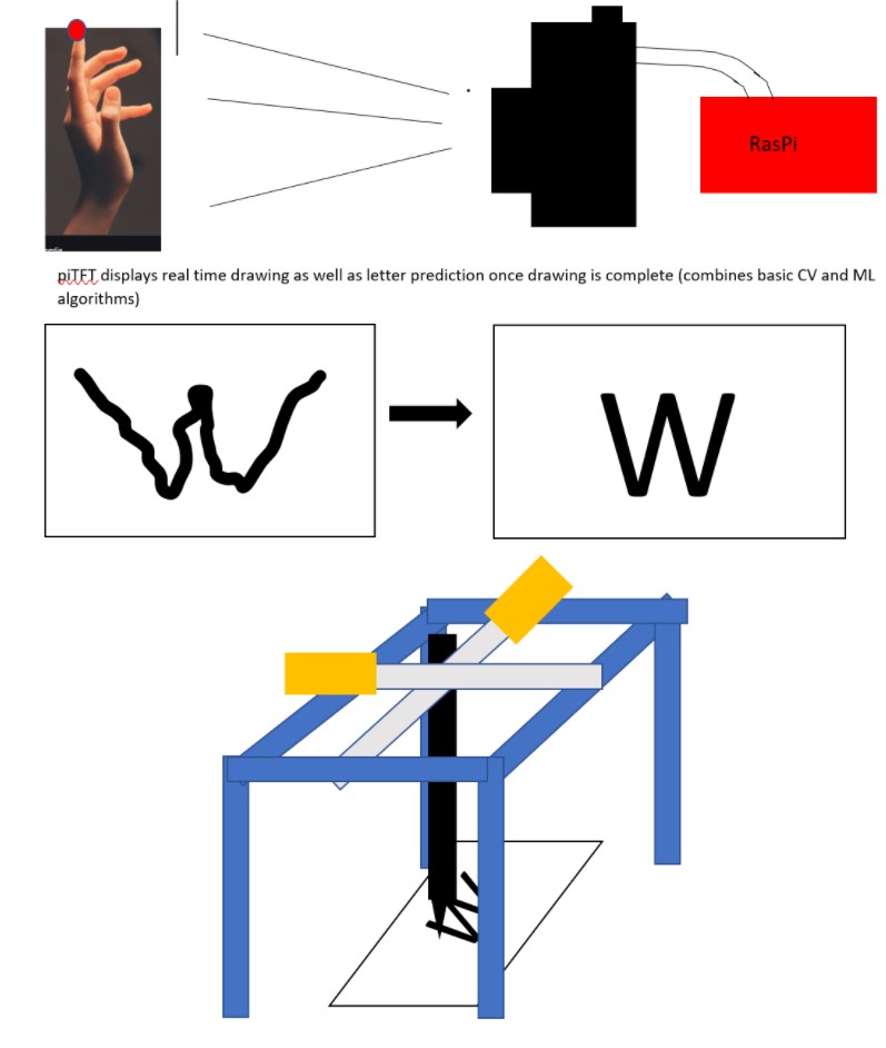
The personal note writer was intended to be a tool to print out user inputs drawn onto a canvas. Gesture control and vision tracking allowed the user full control of a user interface directly connected to a 2D plotter for immediate output. The goal was to use a self trained machine learning model to recognize words (or numbers) written on the canvas and print their outputs in regular typeface. The inclusion of math and word models would make word identification as well as solving simple arithmetic possible.
Introduction
The team created a compact drawing interface controlled by vision tracking and gesture recognition. The interface is connected directly to a 2D plotter which takes image input, mapped to an array of vectors, and translates those vectors into 3-axis motion of a pen. The x and y axis were used for drawing and the z-axis was used to lift the pen off the paper and put it back down when necessary. A significant effort was directed at getting the character recognition models working. Though they worked well offline (not on the Raspberry Pi but on local machines), package incompatibility meant that the team needed to make the hard decision to cut it from the project. In any case, the work that went into building the models will be discussed here so that later iterations of the design can focus more heavily on model integration.
Design and Testing
The original design was based on the following diagram. Most of the core functionallity was maintained going forward. Below we'll talk about the steps we took to make each stage of this process happen, as well as what worked well and what did not.
User Interface and Gesture Recognition
The hand detection model was initially developed using basic image processing algorithms. The approach closely aligns with the one taken in Air Painter. The idea was to adapt this algorithm for the needs of our project. The raspberry pi has an in-built camera serial interface (CSI) to host camera modules. The standard camera module uses a Sony IMX219 image sensor. It is an 8-megapixel sensor that can capture video at Full HD resolution at 30 frames per second (FPS). The installation of the standard camera module was quite straightforward. The only change required after inserting the camera in the appropriate port was to enable the camera in raspberry pi’s configuration settings. The video is streamed live using the WebcamVideoStream method of the imutils library. The output is directly compatible with the OpenCV library that is used for applying various image processing algorithms.
The background is first subtracted from the image using Otsu segmentation method with cv2.threshold(). Next, we found contours present in the image and removed the background to focus on the hands. The image is then passed to cv2.ConvexHull() method to map the shape of the hand. The output has to provide enough markers to locate the fingers and other keypoints in the hand. However, the whole approach fell apart when the background is non-uniform and the output is inconsistent with slight variations in the image. We decided to change the camera hoping that a better camera will resolve this issue.
C920 is a Full HD resolution webcam with 30 FPS. In addition, it has a five-element glass lens to capture sharp images and autofocus for a consistent definition of video. The setup of C920 was also hassle-free. No additional drivers were installed on the raspberry pi. The webcam was connected to one of the USB ports (2.0 or 3.0) of the raspberry pi. However, the new camera offered very little in terms of performance improvement. Though the quality of video stream with the C920 webcam is better than the standard camera module, the algorithm is unable to detect the hand and in turn the keypoints.
At this moment, we resorted to a more advanced computer vision algorithm based on deep learning. MediaPipe provides highly-optimized machine learning models for a number of computer vision tasks. The current method uses a hand detection model followed by a high-fidelity finger tracking model. The hand detection model is a single-shot detector that is optimized for usage on edge devices. The model first detects and localizes the rigid parts of the hand, like palm and fists, using a bounding box (or anchor). It then applies a non-maximum suppression algorithm to get the optimal number of bounding boxes. The model minimizes a focal loss function during training. It achieves 95.7% accuracy for palm detection. Once the palm is detected and localized using a bounding box, the algorithm finds 21 3D keypoints on the hand using a hand landmark model. These keypoints will help us to identify different types of fingers and their spatial orientation in the image.
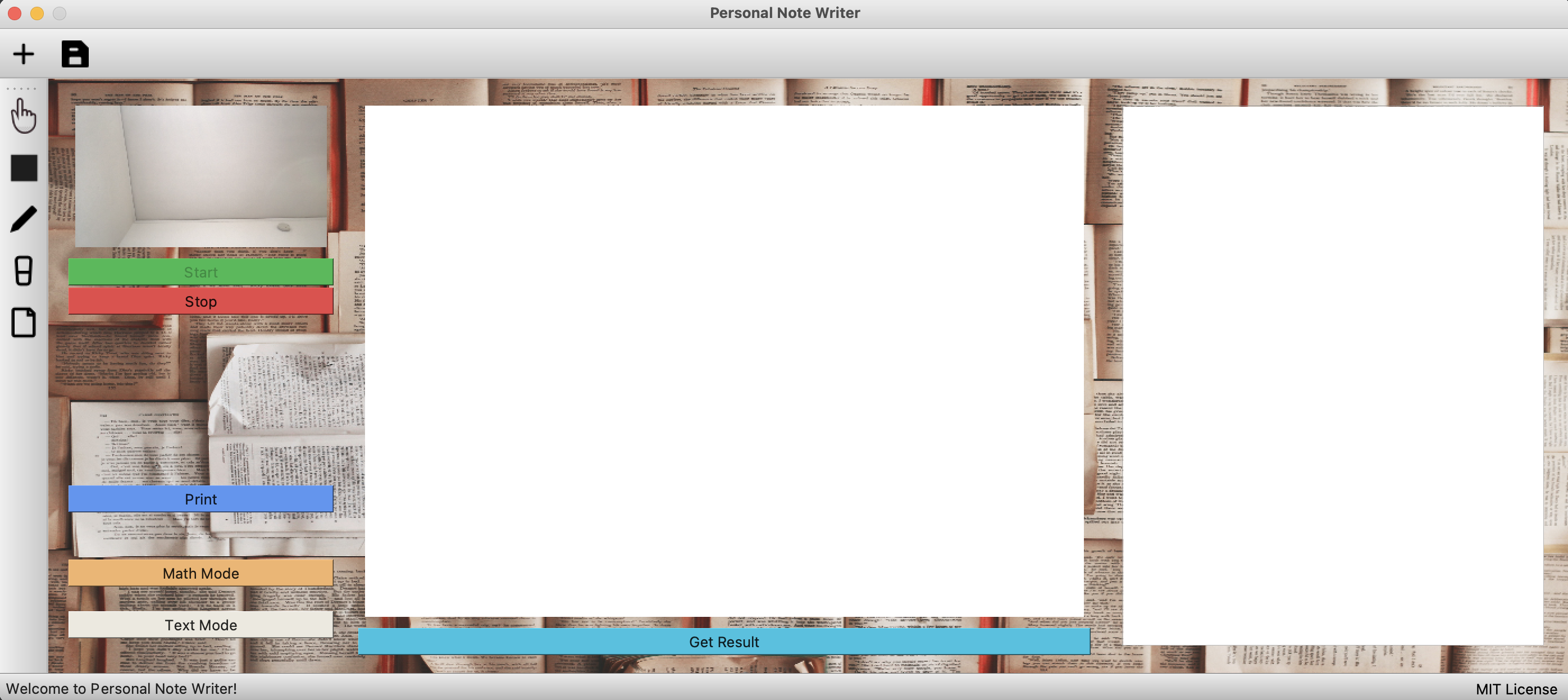
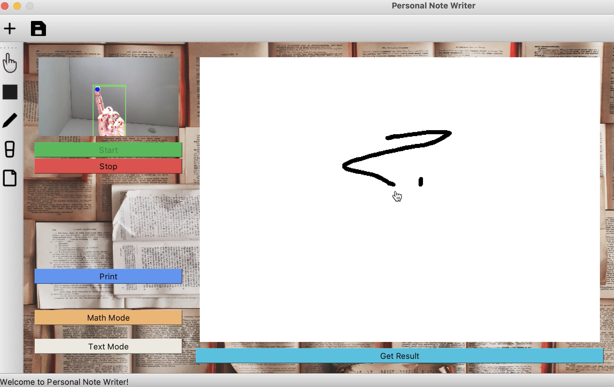
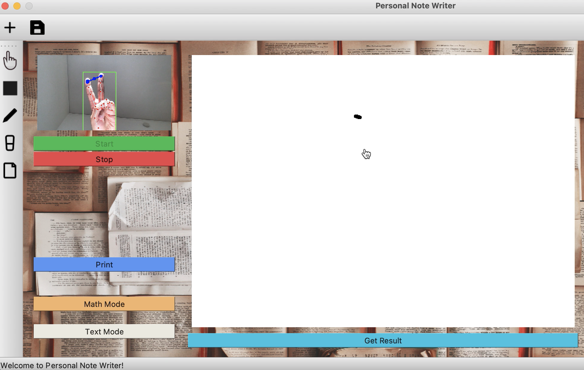
The user interface brings together all the parts of the project in one place. The idea was to provide a common and easy-to-use interface for the user to interact with the project.
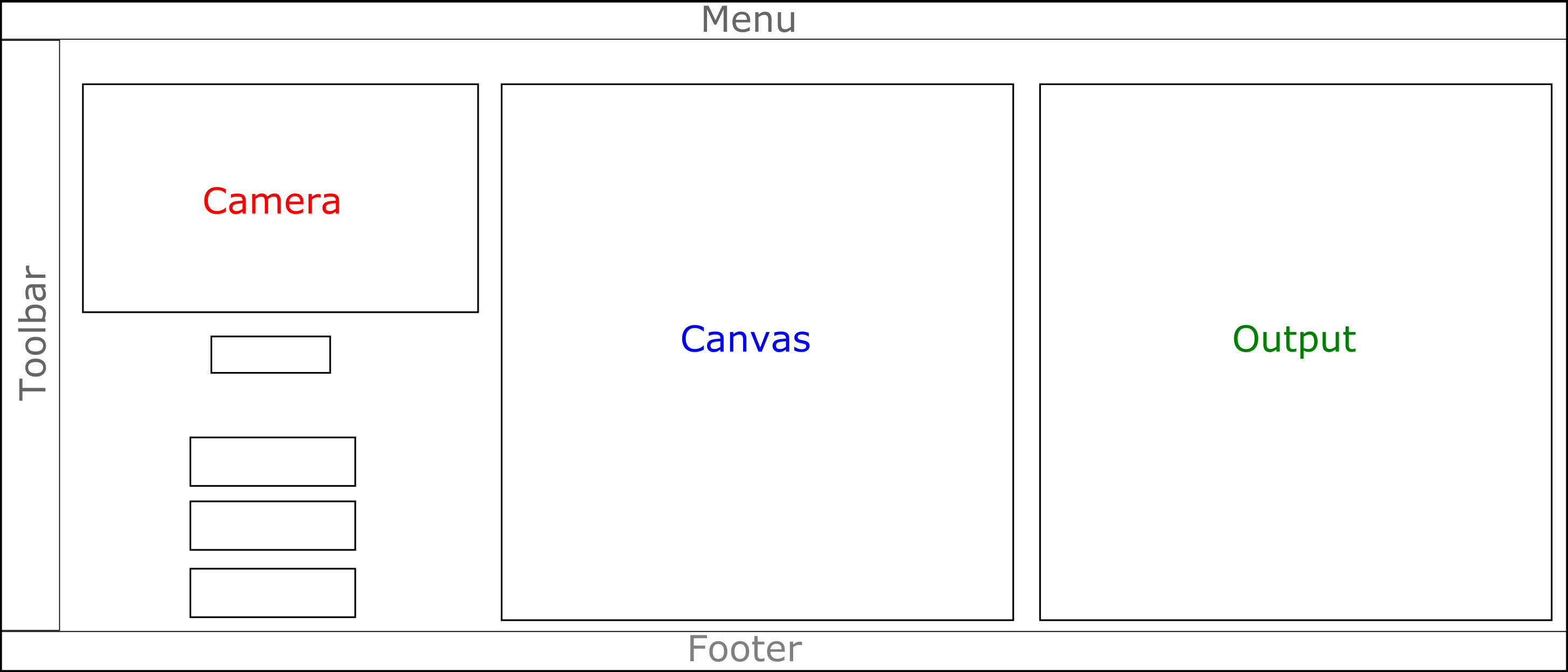
The GUI was designed using PyQt5, a python binding of the popular GUI development framework called Qt. It offers cross-platform support for about 620 widgets and extends itself for advanced GUI applications such as network communication, databases, and web browsing. The layout of the GUI used for the project is shown in the Figure above. The toolbar provides different options for drawing on the canvas.
The GUI emulates a finite state machine for different modes of the project, namely print mode, text mode, and math mode. It exploits the multi-core feature of raspberry pi and delegates the events related to the camera that might require significant computational resources to a different thread. This makes the GUI steadfast and independent of relatively high-latency computation of vision algorithms. The pyautogui library allows mouse event handling using the coordinates of fingertips provided by the computer vision algorithm.
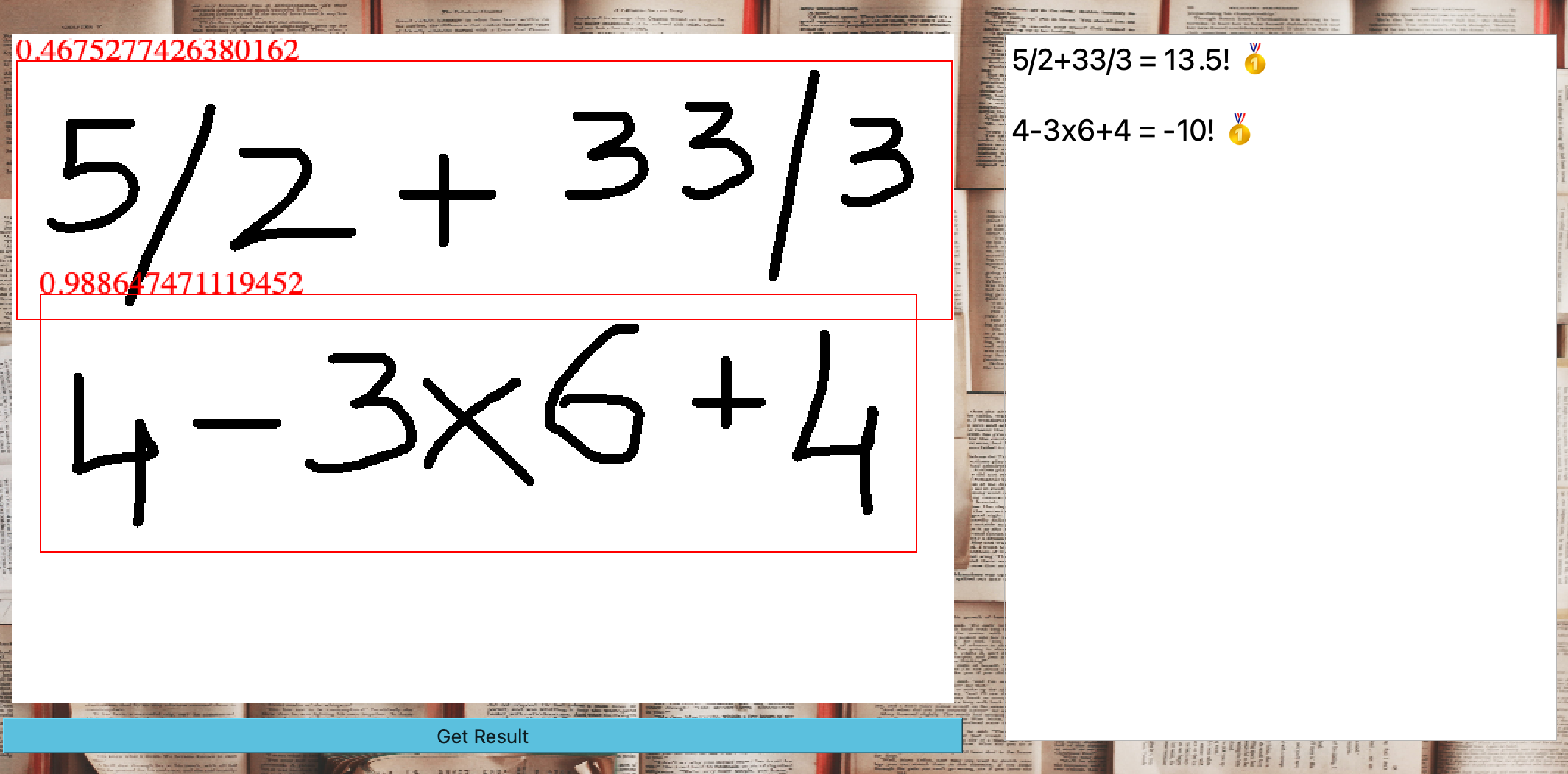
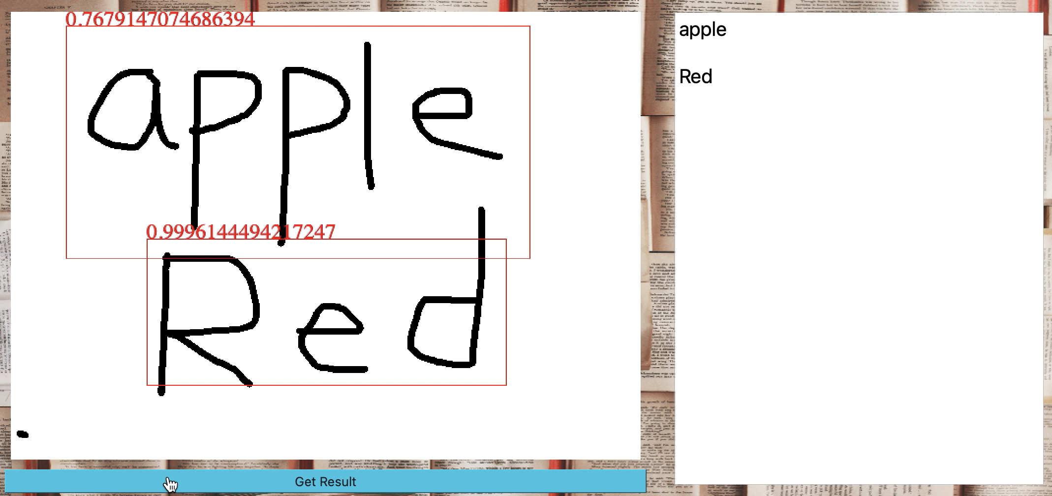
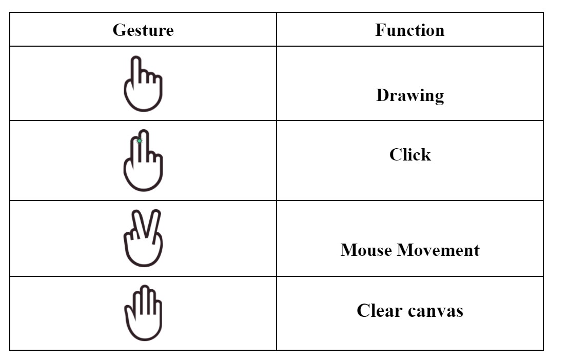
Once the camera starts, the user can draw on the canvas using the index finger. To just move the mouse over the GUI, both index and middle fingers should be lifted. However, in this case, the vision algorithm only tracks the index finger to avoid unintentional scribbles while switching to drawing. When these two fingers (index and middle) are brought together a mouse click event is triggered. If one wants to clear the canvas, all five fingers should be lifted simultaneously. In this way, the user can interact with the GUI and control the raspberry pi hands-free—using fingers. The ‘Get Result’ button triggers the application of optical character recognition on the canvas when clicked. The result gets displayed in the window next to canvas depending on the mode. In the math mode, the program evaluates the expression on the canvas and displays the result. In text mode, the program will translate all the written text on the canvas into a typed format. The result can also be printed using the print button. The result of the math mode and text mode is shown in the figure below. We tried to use some open-source packages for character recognition. The simpleocr package performed well for our setup. The results are shown in Figure [] (refer to the ocr figures in the user interface section). However, we were unable to translate the same onto the raspberry pi since PyTorch on which the package is dependent requires 64-bit OS while the raspberry pi we are using is a 32-bit OS. Another package called Pytesseract works poorly on handwritten texts. It was intended to recognize only typed text, which does not serve our purpose. Therefore, the character recognition was left for future work. This result is obtained on a local machine and provided as reference for future work.
Printer Hardware
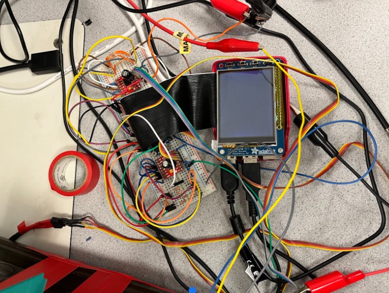
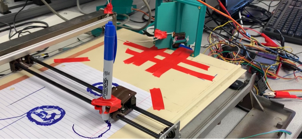
We salvaged an old plotter taken from the 2018 ECE 4760 banana scan project and converted it into a 2D printer. The image below shows the printer setup with the Raspberry Pi, motor control circuitry, and power supplies
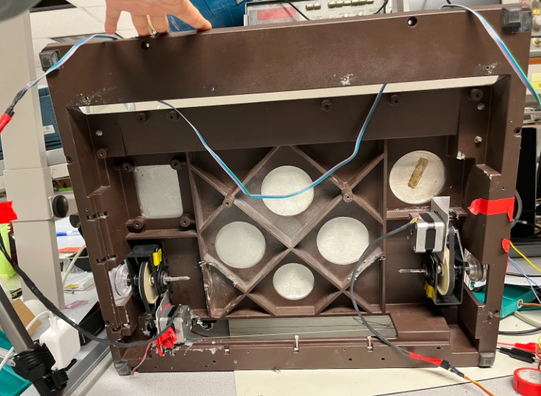
We started off by removing the unnecessary components from the salvaged plotter and fixing broken wire connections. There were several wires that were severed or not properly connected to its respective pin connector, so we re-soldered the connections and used the voltmeter’s continuity check function to ensure that connections were continuous. Once this was done, we used electrical tape and shrink wrap to prevent any shorts between the wires.
Drawing on a plotter requires accurate positioning, and stepper motors are great for fine-tuned, precise control. Stepper motors have four coils that alternate to spin the motor. Different stepping patterns can vary the rotation speed and power consumption of the motor. Single stepping uses a single coil to hold the motor in place. Double stepping activates two coils to rotate the motor with more torque. Interleaved stepping mixes single and double steps for smoother transition between steps. Microstepping mixes single stepping and PWM for smooth step transitions and for high precision control. For the Nema 17 that we’re using, each stepper has four wires - two wires activate one coil in the motor. For this project, we used a half stepping pattern to actuate the stepper motors, which will be described later.
Two stepper motors and a motor shield came with the plotter. According to previous documentation, the driver shield is the Adafruit DC & Stepper Motor HAT for Raspberry Pi, and the stepper motors are assumed to be the Nema 17 motors. The motors were not detached from the plotter to confirm the type and part number because we did not want to break the setup. To test the motors, we imported the adafruit_motorkit library and used functions from a stepper class to control motor direction and stepping pattern. The motor shield was powered with a 12V power supply source, with a max 2A output. When testing, a problem we ran into was that the DC power supply would oscillate between the constant current and constant voltage function. The board got very hot and smelled burnt at times, and we found one of the motor channels had shorted. Due to this, we were not able to continue using the HAT and had to switch to an alternative implementation.
We switched to using two Sparkfun TB6612FNG dual channel motor controllers from the Lab 3 robot to actuate the two stepper motors. The diagram below shows the controller pinout. For the two-coil stepper motor, the Aout and Bout pins are connected to a respective coil, and the output signals generated high and low values to rotate the motor. The pins are connected to the GPIO pins of the Raspberry Pi. The specific pins are shown below, as well as a full circuit schematic. The circuit build was based on a Raspberry Pi stepper motor tutorial, which used a different driver, but had the same purpose. The 100uF capacitor is connected between the positive and negative terminals of the driver to protect the board from sudden voltage/current changes. See the circuit diagram for the setup below.
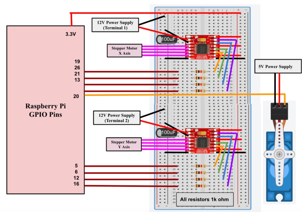
To run the steppers, we used an RpiMotorLib library from https://github.com/gavinlyonsrepo/RpiMotorLib and ran the test file in the repository. In this file, there were six tests with varying stepping sizes. One problem we ran into was that the motor would click between two positions, but it would not rotate. We used the oscilloscope to check the signal outputs and found that the Aout and Bout signals were square waves in phase with each other. This meant that the coils were activating at the same time, which is why the motor would not spin; the coils need to alternate to generate rotational motion. We resolved this by hardwiring the PWMA, PWMB, and STBY pins to logic high (3.3V), and the oscilloscope showed a slight phase shift between outputs, which is what we expected for the motor to continuously rotate. The servo controls the z direction of the plotter and determines when the pen is touching the paper. It is connected to pin 20 on the Raspberry Pi, powered by an external power supply, and controlled via PWM.
Printer Control
Printer control presented one of the largest challenges of the project. Given the setbacks in the printer hardware design, it was not immediately clear the team was going to be able to get the printer running at all. Luckily, the rpigpiolib library provided functionality compatible with both the TB6612FNG motor controllers, and the NEMA-17 steppers.
Before the team could think about direct servo control, we needed to consider how to get from an image to something that could be translated into 2-axis linear motion. Initially, we gravitated towards using an image-to-gcode converter. G-code is an easily interpreted language used by 3D printers, 2D plotters, CNC routers etc., which tells a printer how to move, when to pause, when to print, and everything in between. The problem we realized with this strategy was that all these printers and routers generally have firmware that is set up to interpret certain types of g-code (of which there are many). Our printer had no processor, or any circuitry at all. We would have to implement our own software g-code interpreter. Converting from image → gcode → stepper commands with a self implemented g-code interpreter seemed like a roundabout method that added extra steps to the process.
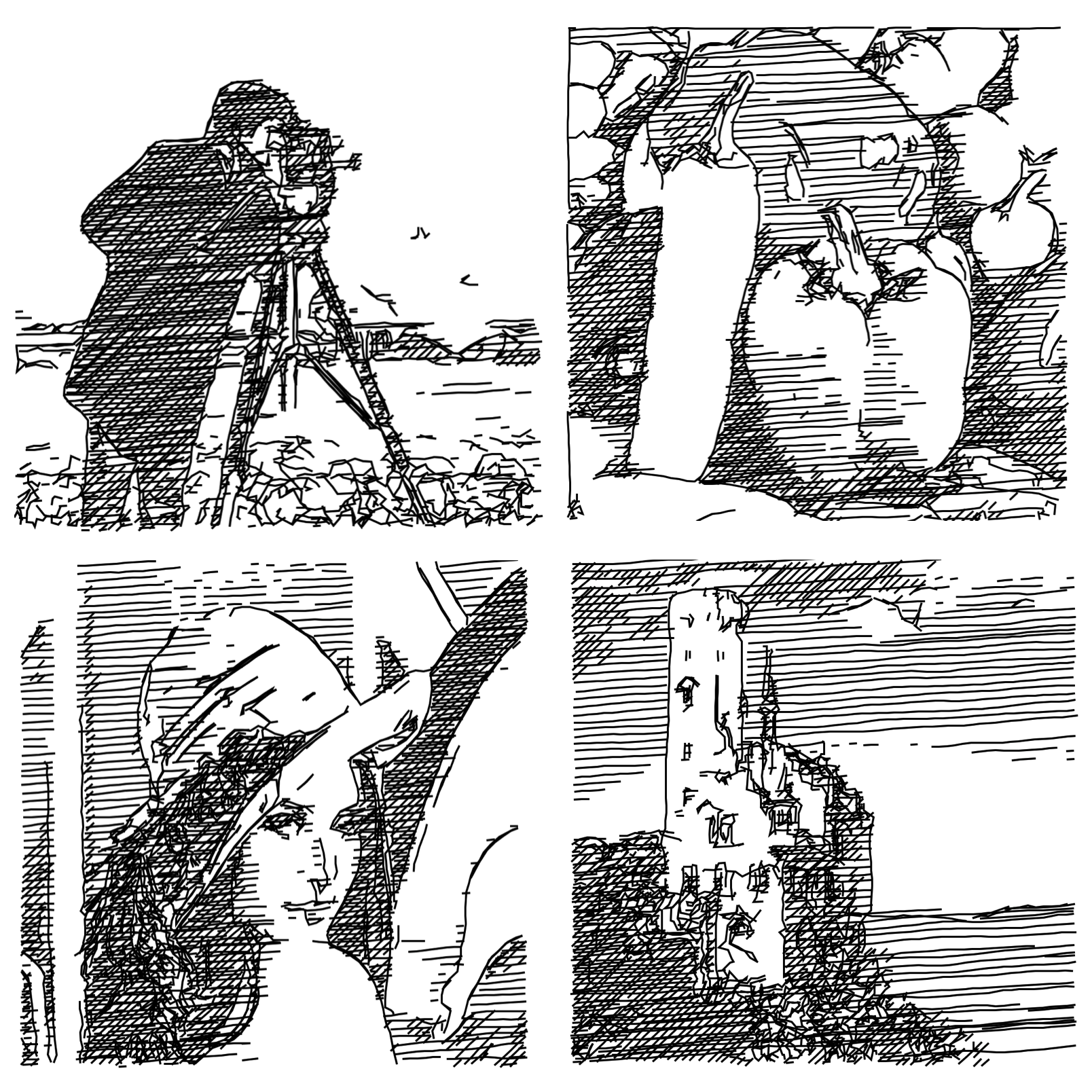
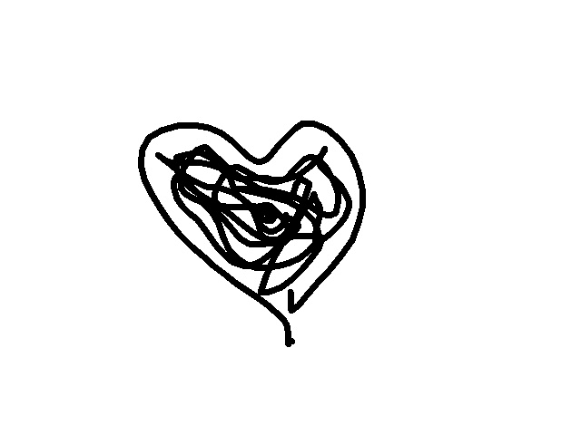
After much looking, we found a library on github, at https://github.com/LingDong-/linedraw/blob/master/README.md that produced an svg file of lines given an input image, which made the input image look like a sketch. The script handled drawing “fill” in a similar way to how a 3D printer would handle solid objects. It’s simply inefficient to fill in the whole thing, so it generates some representative inner structure to limit the filament used while maintaining the integrity of the structure. The linedraw library produced a similar “fill” for thick lines, such that there was clearly white space in areas that were fully black in the image, but which maintained the overall integrity of that section. An example output from the repository’s README is shown below.
def visualize(lines):
    import turtle
    wn = turtle.Screen()
    t = turtle.Turtle()
    t.speed(0)
    t.pencolor('red')
    t.pd()
    for i in range(0,len(lines)):
        for p in lines[i]:
            t.goto(p[0]*640/1024-320,-(p[1]*640/1024-320))
            t.pencolor('black')
        t.pencolor('red')
    turtle.mainloop()
From this function, we were able to determine where the “lines” argument was being produced. After some analysis, it became clear that lines was a three dimensional array of points. The first dimension was the line. The second dimension was a point in each line and the third dimension defined the x and y coordinates of that point. Essentially lines was a list of continuous lines. Continuity helped us greatly here, because we could iterate over the list of lines to control the stepper motors, and every time we hit a new line, that would indicate that the pen needed to be lifted. In the code block above this moment is defined as the point when the pen color is set to red. The visualizer was helpful in that it provided the skeleton code for iterating over this list of lines to produce the servo movements. Our code block for printer control is shown below. Following it is a breakdown of how each line contributes to printer motion.
def print_drawing(lines):
    global x_gate
    global y_gate
    global x_turn
    global y_turn
    servo = Servo(20)


    # GPIO.setwarnings(False)
    # GPIO.setmode(GPIO.BCM)
    # GPIO.setup(20,GPIO.OUT)
    # p = GPIO.PWM(20,50)
    servo.value = -1
    sleep(0.5)


    Motorname = "MyMotorOne"
    Motortype = "Nema"
    x_motor = RpiMotorLib.BYJMotor(Motorname, Motortype)
    A11 = 19
    A12 = 26
    B11 = 21
    B12 = 13
    GpioPins = [A11, B11, A12,B12]

    Motorname2 = "MyMotorTwo"
    Motortype2 = "Nema"
    y_motor = RpiMotorLib.BYJMotor(Motorname2, Motortype2)
    A11_2 = 5
    A12_2 = 6
    B11_2 = 12
    B12_2 = 16
    GpioPins2 = [A11_2, B11_2, A12_2, B12_2]

    verbose= False
    steptype = "half"
    initdelay = 0.001

    paper_res = [800,400]
    pen_up = True
    start_pos = [0,0]
    absolute_pos = [0,0]
Here we initialize all necessary variables. You’ll notice that we were initially using hardware PWM control but transitioned to a library that made it a little bit easier. The servo we were using was very cheap and was not responding well or even consistently to the PWM pulses we were sending. As such, we started using the gpiozero library. The line servo = Servo(20) initializes a servo object at GPIO pin 20, and setting the servo value to -1 ensures that the pen is lifted off the paper at start. The servo lifts the pen by pulling a bar attached to the printer.
Following are the stepper motor initializations for the rpigiolib library that allow us to automatically control stepper motor actuation. Absolute_pos is an extremely important parameter. It keeps track of the absolute position of the printer head over the duration of the print, and ensures that it can return to a certain position in the drawing (which often happens) to draw new lines or keep filling. Now comes the iteration over the lines argument. First we only interate over each continuous line... later we will iterate over each point in that continuous line. It's broken up this way so that the code can tell exactly when the pen needs to be lifted.
    for i in range(0,len(lines)):

        #defining movement vectors from the end of the old line to the start of the new line
        #the pen is lifted because we are moving between continuous lines, not within a continuous line
        new_line_x = (lines[i][0][0] - absolute_pos[0])
        new_line_y = (lines[i][0][1] - absolute_pos[1])
        #update the absolute position
        absolute_pos[0] += new_line_x
        absolute_pos[1] += new_line_y

        #This one is interesting
        #We found the x and y axes behave differently given the same number of stepper motor steps
        #The pully system on the y axis was significantly stiffer, manually account for this
        steps_x = abs(new_line_x)//2  # No of step sequences
        steps_y = abs(new_line_y)//1.5

        #define motor speeds so that neither x or y finsishes moving without the other
        if abs(new_line_x) > abs(new_line_y) and new_line_x != 0 and new_line_y != 0:
            x_wait = 0.001
            y_wait = 0.001 * abs((new_line_x/new_line_y))
        elif new_line_x != 0 and new_line_y != 0:
            y_wait = 0.001
            x_wait = 0.001 * abs((new_line_y/new_line_x))
        else:
            pass

        #define movement direction based on the sign of each vector
        if new_line_x > 0:
            x_turn = True
        else:
            x_turn = False

        if new_line_y > 0:
            y_turn = True
        else:
            y_turn = False

        #defining callback functions for the x and y motion - this is so we can thread the processes
        def new_x_motion():
            global x_turn
            global x_gate
            x_motor.motor_run(GpioPins ,x_wait ,steps_x ,ccwise = x_turn ,verbose = False, steptype = 'half' ,initdelay = 0.001)
            x_gate = False

        def new_y_motion():
            global x_turn
            global y_gate
            y_motor.motor_run(GpioPins2 ,y_wait ,steps_y ,ccwise = y_turn ,verbose = False, steptype = 'half' ,initdelay = 0.001)
            y_gate = False

        #start the thread - lets x and y move at same time
        Thread(target = new_x_motion).start()
        Thread(target = new_y_motion).start()

        #prevents execution of next movement until the threads are completed - enforces movements happen
        # in the order that they should
        while x_gate == True or y_gate == True:
            pass

        #move the servo to place the pen down
        servo.value = 0
        sleep(0.5)
Now, at the start of each continuous line the printer head needs to be moved from the end of the last continuous line to the start of the new one, all without drawing. This is handled using the first position in the lines vector as well as the absolute position of the printer head. A resultant movement vector is calculated, Stepper speed and direction is determined next, and callback functions for the x and y motion are defined. The reason callbacks are necessary here is that moving both steppers at the same time (ie. making diagonal lines) is impossible with the rpigpio library unless you take advantage of threading in python. The motor_run function handled by the library prevents the execution of any subsequent code until it is completed. As such, we used threading to allow simultaneous x and y motion defined by the vectors calculated previously. The script falls into a while loop that doesn’t pass until the threads have been completed. This ensures that we don’t start the next movement too early. Now that the printer head is at the start of a new line, it is moved down by the servo to touch the paper. It is now time to move between points within the line.
        # iterate over the points in each line - pen will remain down the whole time
        for j in range(len(lines[i])-1):


            #used for while loop control
            x_gate = True
            y_gate = True
            print(lines[i])

            #calculate movement vector
            mov_x = (lines[i][j+1][0] - lines[i][j][0])
            mov_y = (lines[i][j+1][1] - lines[i][j][1])
            print(mov_x)
            #update the position
            absolute_pos[0] += mov_x
            absolute_pos[1] += mov_y


            steps_x = abs(mov_x)//2 # No of step sequences
            steps_y = abs(mov_y)//1.5

            #properly set servo speed (Same as above)
            if abs(mov_x) > abs(mov_y) and mov_x != 0 and mov_y != 0 :
                x_wait = 0.001 * 2
                y_wait = 0.001 * abs((mov_x/mov_y))
            elif mov_x != 0 and mov_y != 0:
                y_wait = 0.001
                x_wait = 0.001 * abs((mov_y/mov_x)) * 2
            else:
                pass

            #set movement direction (same as above)
            if mov_x > 0:
                x_turn = True
            else:
                print('here')
                x_turn = False

            if mov_y > 0:
                y_turn = True
            else:
                y_turn = False


            #callback functions for x and y motion, same as above
            def x_motion():
                print('x step confirmation is' + str(mov_x))

                global x_turn
                print('x turn is' + str(x_turn))
                global x_gate
                x_motor.motor_run(GpioPins ,x_wait ,steps_x ,ccwise = x_turn ,verbose = False, steptype = 'half' ,initdelay = 0.01)
                x_gate = False

            def y_motion():
                global y_turn
                global y_gate
                y_motor.motor_run(GpioPins2 ,y_wait ,steps_y ,ccwise = y_turn ,verbose = False, steptype = 'half' ,initdelay = 0.01)
                y_gate = False

            #start the thread

            Thread(target = x_motion).start()
            Thread(target = y_motion).start()

            #hold in while loop until the threads are complete

            while x_gate == True or y_gate == True:
                pass

            x_gate = True
            y_gate = True

        #this continuous line has finished, lift the pen
        servo.value = -1
        sleep(0.5)
This block of code is almost the exact same as the one described previously, with one major difference. The movement vector calculated at the beginning of the loop is now the difference between the next point and the last point within the same line. As such, the pen should remain on the paper at all times. When this loop is completed, the code moves back up to the first loop to start a new line, but not before lifting the pen off the paper again. When the whole image has been drawn, the printer head returns to its start location. “Start location” in this case is a bit arbitrary and its set by the user at the beginning of the run just by pushing the printer head. Given more time we could’ve added a calibration step involving sensors, but stepper motors give no positional feedback by themselves.
The printer works better on some images than others. For example, here are two products of printing and their source images.
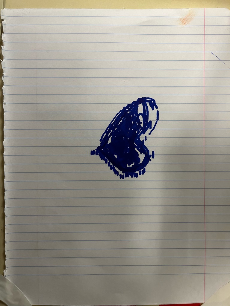
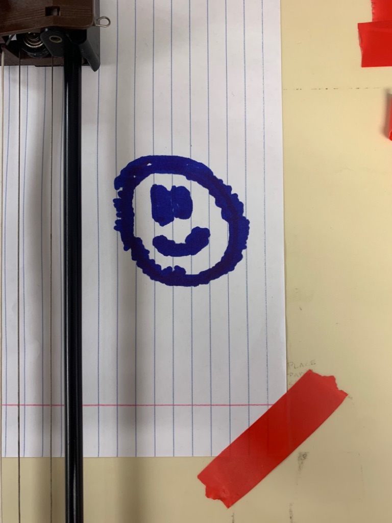
Though the overall shape is maintained to some level of detail, there are a number of distortions in the resultant images that should be explained. First, the y axis appears to be slightly compressed in the prints relative to their source images. This is due to the differences in the x and y axis. Just by feeling the printer head, its immediately clear that the y-axis is significantly stiffer than the x. As a result, we noticed that for a given step in y in and x, the x direction moved about 1.5x as far (but not exactly 1.5x). As such, we manually scaled the y movements in the control code. The effect still lingers to a minimal degree. The second effect is the fill lines not lining up exactly with the outlines. This is most noticeable in the image of the heart where the fill lines on the right side don’t exactly line up. We think that this is again due to the relatively imprecise way the printer head is driven through a complex pulley system. We’ve noticed that the belts driven by the stepper motors sometimes slip on the pulleys. The compounding of these effects leads to misprints like this.
Character Prediction Model
As stated previously, one of the initial goals of the project was to implement our own neural network to help with character recognition. Though we couldn’t get the model to run on the Raspberry Pi, below is the process we used to generate and test the model. The neural network was trained on the website Kaggle, a data science platform for developing in Python with free access to GPUs for training large models. We never planned to train anything on the Pi, it simply does not have the computational resources. By using the TensorFlow library, we can produce a parametrized model, and save it to an h5 file. This h5 file, containing a list of optimized parameters for handwriting recognition, could then be uploaded onto the pi and used to evaluate handwritten characters. The data set we used is the well known EMNIST dataset which contains hundreds of thousands of preprocessed images of handwritten characters.
testing_letter = pd.read_csv('/kaggle/input/emnist/emnist-letters-test.csv')
training_letter = pd.read_csv('/kaggle/input/emnist/emnist-letters-train.csv')

#establish training labels and images
y1 = np.array(training_letter.iloc[:,0].values)
x1 = np.array(training_letter.iloc[:,1:].values)
x1 = x1.reshape((x1.shape[0], 28, 28, 1))

#establish validation labels and images
y2 = np.array(testing_letter.iloc[:,0].values)
x2 = np.array(testing_letter.iloc[:,1:].values)
x2 = x2.reshape((x2.shape[0], 28, 28, 1))
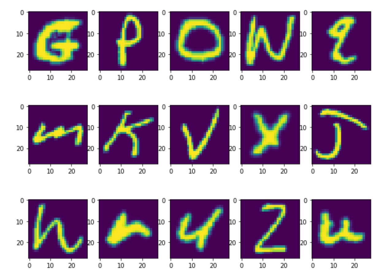
The dataset can be directly loaded from kaggle, another benefit of the site. The images come as preprocessed 28x28 images of both upper and lowercase handwritten characters. Below is a example of a few of the loaded images. Loading the dataset itself was a challenge but an example using the same dataset by _____ was used here.
After a little bit of additional processing, the neural network was defined as follows, with three convolutional layers and two dense layers which contain the actual parameters to be optimized.
def define_model():

	#defining the parameters of a neural network with 3 convolution layers and 2 dense layers
	#the dense layers are the actual parameter producing portion of the network
    model = Sequential()
    model.add(Conv2D(32, (3, 3), activation='relu', kernel_initializer='he_uniform', input_shape=(28, 28, 1)))
    model.add(MaxPooling2D((2, 2)))
    model.add(Conv2D(64, (3, 3), activation='relu', kernel_initializer='he_uniform'))
    model.add(Conv2D(64, (3, 3), activation='relu', kernel_initializer='he_uniform'))
    model.add(MaxPooling2D((2, 2)))
    model.add(Flatten())
    model.add(Dense(100, activation='relu', kernel_initializer='he_uniform'))
    model.add(Dense(27, activation='softmax'))
    # compile model

    #optimize model during every epoch with stochastic (essentially random direction) gradient
    #descent by minimizing the cross entropy loss
    opt = SGD(learning_rate=0.01, momentum=0.9)
    model.compile(optimizer=opt, loss='categorical_crossentropy', metrics=['accuracy'])
    return model
During every training “epoch” the model takes a step with stochastic gradient descent to attempt to minimize the cross entropy loss by updating the parameters in the model. There are several loss functions that can be minimized in TensorFlow but cross entropy is popular for convolutional neural networks. During training we made 10 epochs or ran through the model a total of 10 times to optimize the parameters.
    model = define_model()
    # fit model
    model.fit(trainX, trainY, epochs=10, batch_size=32, verbose=0)
    # save model
    model.save("letter_model.h5")
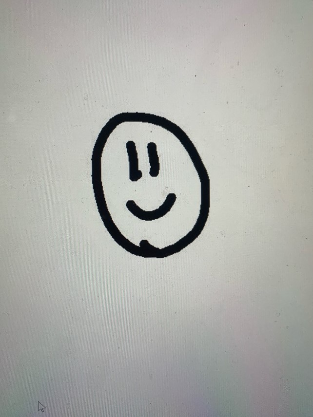
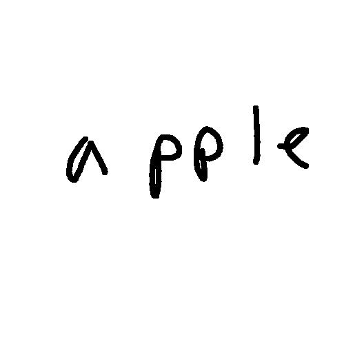
Finally the model was trained on the EMNIST dataset and saved to letter_model.h5. Now in order to evaluate that model on the drawing canvas implemented in the GUI, we needed to be able to take an image, parse it for characters, preprocess each character image to make it look as similar as possible to the testing data, and then evaluate. Take the image below:
We need to iterate letter by letter and evaluate the model to eventually return a typeface version of what is written on the canvas.The code for this process can be found in evaluate_models.py in our repository and was adpated from code by Adrian Rosebrock [1]. The output of that script is shown below:
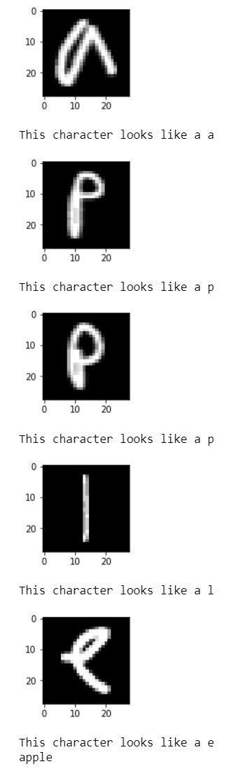
Clearly the recognition works well, so where did we go wrong? Well in order to evaluate a test point on the h5 file, you need TensorFlow to be installed on the Raspberry Pi. Given the rapid updates to both the operating system we're working with, and TensorFlow itself, we were unable to get it correctly installed. It seemed like it was almost working, but some of the dependencies for the library were incompatable with the operating system we were working with. We were met with a lot of dead installation links. Given more time, future work should include getting TensorFlow installed correctly, because it would add significantly to the project.
Conclusion
This project covers a wide range of topics from the applications of machine learning models, and GUI development, to motor control on a Raspberry Pi. The team successfully employed a hand recognition feature to track fingers by leveraging multi-processing on the raspberry pi. Hand gestures will trigger different mouse control events for drawing, clearing the screen, printing, etc. The printer, with the help of servo and stepper motors, reproduces the image onto a sheet of paper from a point map of the image. Overall the group learned a lot from the experience. We were all very happy with how the project turned out given the time constraints.Future Work
Given more time, we would have liked to implement the character recognition part on raspberry pi. Installing TensorFlow and deploying it effectively are the crucial next steps. The recognition model is already in place and would be easy to integrate afterwards. In addition, we noticed some belt slippage on the y axis motor. While the slippage was fairly minimal, it was not ideal for large drawings and drawings with curves, as the continuous build up of offsetted lines would significantly distort the image. Given more time, we would experiment with different stepping sizes for smoother step transitions as well as increase the spacing between the belt and motor for reduced slippage. In addition, we would also consider designing and 3D printing a pen holder that could hold different sized stationary (pen, pencil, market, etc).
Project Logistics
This project was completed in fall of 2021 as a required project for ECE 5725 (Embedded Operating Systems) at Cornell Univeristy in the department of Computer and Electrical Engineering.
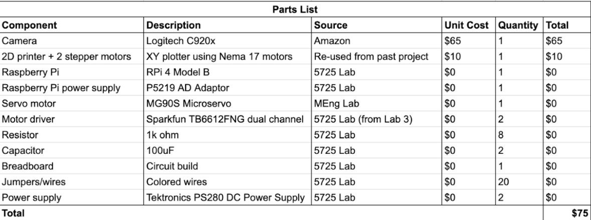
The total cost came out to $75. The primary source comes from the $65 Logitech C920x camera, as we needed a camera with a high resolution to capture hand gestures. The rest of the supplies and parts used came from the lab.
Acknowledgements
We would like to thank Prof. Joseph F. Skovira (jfs9) for his extended support and guidance throughout the course of the project. We also appreciate the time and assistance of TAs whenever required to bring the project to its present form.
Code Appendix
https://github.com/asaidarahas/Personal-Note-Writer
References

Peter McGurk (pjm326@cornell.edu) is an M.Eng student in the department of Electrical and Computer Engineering at Cornell University. He was involved with character recognition model development, and printer control software.

Frances Lee (fl296@cornell.edu) is an undergraduate senior in the department of Electrical and Computer Engineering at Cornell University. She was involved with printer hardware development and circuitry.

Sai Darahas Akkineni (sa754@cornell.edu) is is an M.Eng student in the department of Electrical and Computer Engineering at Cornell University. He was involved with GUI development and computer vision applications.